Installation
and Maintenance
Installation
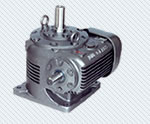
Gearboxes are to be rigidly mounted
so as to minimize the effect of fluctuating or heavy
loads. Always check the alignment after bolting down.
After installation and alignment has taken place,
properly locate the gear unit by means of dowels at
appropriate locations preferably in diagonal direction.
The use of flexible couplings (Love joy / Gear coupling
flanges with rubber bushes/tyre couplings) is very
important for the improved performance of the gearbox.
The couplings are to be lined up to avoid the misalignment
of angularity and eccentricity.
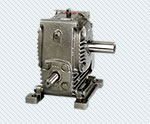
Change of Handing
When changing the handing of the
slow shaft extension, the shaft complete with worm
wheel, bearings etc. should be reversed as a unit.
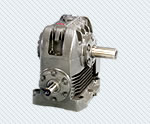
It should be appreciated that this has the effect
of reversing the offset of the wheel relative to the
worm. When changing the slow speed shaft handing of
V type units, it should be noted that the position
of the wheel relative to the case must not be changed;
it is necessary therefore to press the wheel from
the shaft. The position of the shaft in relation to
the worm wheel must be reversed. The end covers should
be located in their respective positions.
It is necessary to check contact markings on the worm
wheel teeth and if any axial adjustment of the worm
wheel is necessary, it can be effected by means of
the shims between covers and bearing housing, which
should be moved from one side to the other. It is
essential that the top half of the gear case be replaced
in its original position (Not applicable for Adaptables).
The contact marking is checked by painting the worm
with red lead of Prussian Blue and rotating the worm
by hand while applying a small breaking pressure to
the wheel by hand. The correct marking should be slightly
heavier on the "leaving side" of the teeth,
relative to the direction of rotation of the worm,
so as to provide "lead in" for the lubricant
and to avoid concentration of pressure on the entering
side as this would affect the smoothness of operation.
 |
Axial
Floats
After re-handing it is essential that shaft
and floats be correctly set. The following axial floats
for wormshaft and wheelshaft are recommended. They
should be checked preferably using a dial
| Size |
Wormshaft (mm) |
Wheelshaft (mm) |
| 112 |
0.050/0.100 |
0.025/0.050 |
| 162 |
0.050/0.100 |
0.025/0.050 |
| 200 |
0.050/0.100 |
0.025/0.050 |
| 237 |
0.050/0.100 |
0.025/0.050 |
| 287 |
0.050/0.100 |
0.025/0.050 |
| 337 |
0.050/0.100 |
0.025/0.050 |
| 300 |
0.050/0.100 |
0.025/0.050 |
| 400 |
0.050/0.100 |
0.025/0.050 |
| 500 |
0.050/0.100 |
0.025/0.050 |
| 600 |
0.050/0.100 |
0.025/0.050 |
| 700 |
0.075/0.125 |
0.025/0.075 |
| 800 |
0.075/0.125 |
0.025/0.075 |
Weekly Inspection
 |
Check the
oil level by means of the dipstick or oil level
plug and add the recommended lubricant to the
level if required |
|
Ensure that
breathers are clean and operating properly, if
blocked clean the breathing holes otherwise pressure
will build up, resulting in oil leakage |
|
Units fitted
with grease nipples, add two or three shots of
grease from grease gun |
|
Regular
oil changes are essential to ensure that the unit
gives long and trouble free service, which depends
upon the following factors |
|
Oil temperature-
under load |
|
Environment-
humidity, dust etc |
|
Operating
conditions- shock loading etc |
|
Replace
the oil as per operating conditions at elevated
temperatures- Refer below |
| Temperature |
Adaptables |
Other Units |
| 75 or Less |
2500 hrs or 6 Months |
5000 hrs or 12 months |
| 80 |
2000 hrs or 6 Months |
3500 hrs or 12 months |
| 90 |
1000 hrs or 3 Months |
1000 hrs or 12 months |